ECO start/stop function
Mercedes Benz 169 - 245 ECO start/stop function with belt-driven starter generator
As of September 2008, the ECO start/stop function, code (B01), will be available as special equipment for the following models of model series 169 and 245:
• A 150 and A 170 with 5-speed manual transmission
• B 150 and B 170 with 5-speed manual Transmission
On vehicles with the ECO start/stop function, the engine is switched off during idle periods. This temporarily eliminates the consumption of fuel and the emission of exhaust gases and noise.
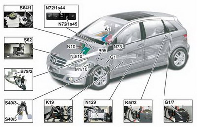
· A1 Instrument cluster
· B64/1 Brake vacuum sensor
· B79/2 Transmission neutral position sensor
· B95 Battery sensor
· G1 Battery
· G1/7 Additional battery
· K19 Battery decoupling relay
· K57/2 Additional battery relay
· M1/10 Starter generator
· N3/10 ME-SFI [ME] control unit
· N10 S AM control unit
· N72/1s44 AS/IRS OFF switch
· N72/1s45 ECO switch
· N73 EZS control unit
· N129 Starter generator control unit
· S40/3 Clutch pedal switch
· S40/5 Start enable clutch pedal switch
· S62 ATA [EDW] hood switch
On vehicles with the ECO start/stop function, the crankshaft is driven by the starter generator via a poly-V belt to start the vehicle.
The use of a belt-driven starter generator has the following benefits:
• Reduction of fuel consumption by approx. 6 to 7%
• Reduction of CO2 emissions to as low as 139 g/km
• Very quiet and quick starting procedure via the starter generator
• Reduction in noise pollution when engine is switched off
The following function requirements must be met for the ECO start/stop function to be activated:
• Engine at operating temperature
• Battery status OK
• Outside temperature in a comfortable range
• Interior temperature close to specified value set on AAC [KLA] control and operating unit, code (580), or comfort AAC [KLA] control and operating unit, code (581).
• Indicator lamp in ECO switch must be on
• Vacuum in brake booster must be sufficient
• Engine hood closed
The ECO start/stop function consists of the following main functions:
• Engine stop function
• Engine start function
• Forced engine start
The engine is switched off by the ME-SFI [ME] control unit when the following function conditions are met:
• Transmission in neutral
• Clutch not actuated
• Service brake operated
• Vehicle speed below threshold value (8 km/h)
The engine is started automatically when the engine was switched off via the engine stop function and circuit 15 is still on.
One of the following function conditions must be met for this to take place:
• Service brake not actuated
• Clutch actuated
• ECO switch actuated
• Vehicle speed above threshold value (8 km/h)
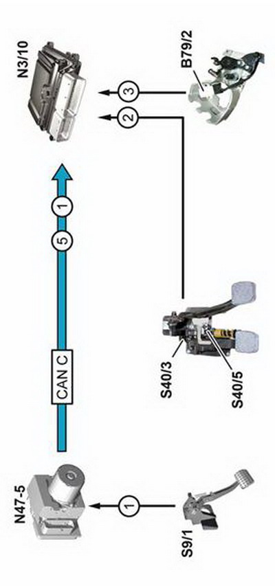
To restart the engine, the ME-SFI [ME] control unit forwards a start signal to the starter generator control unit via the engine compartment CAN. This then actuates the starter generator directly.
The starter generator drives the crankshaft via the poly-V belt. This starts the engine.
The forced engine start function is also available as a protection function. The engine is automatically forced to start by the ME-SFI [ME] control unit without any driver intervention if one of the following function conditions occurs:
• Vacuum in brake booster is not sufficient
• Indicator lamp in ECO switch is not on
• Battery charge level drops below threshold value
Note
On ECO start/stop vehicles, the starting procedure with the transmitter key still takes place via the starter. The function sequence of the starting procedure remains unchanged.
Components
New components
• Starter generator control unit
• Battery sensor on battery
• 12 Ah additional battery (absorbent glass mat battery)
• 70 Ah battery (absorbent glass mat battery)
• Starter generator (replaces alternator)
• Battery decoupling relay
• Additional battery relay
• Hydraulic belt tensioner
• ECO switch
• Transmission neutral position sensor
• Brake vacuum sensor
Modified components
• Wiring harness
• Clutch pedal switch
• Start enable clutch pedal switch
• Modified ME-SFI [ME] control unit
• Modified SAM control unit
• Modified instrument cluster
• Modified poly-V belt
• Modified refrigerant compressor
• Modified ATA [EDW] hood switch
• Water pump and crankshaft belt pulley
• Water pump bearing
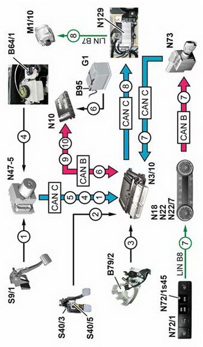
· 1 Brake pedal switch, status
· 2 Clutch switch, status
· 3 Engaged gear, status
· 4 Brake vacuum, status
· 5 Wheel speed signal
· 6 Battery, charge status
· 7 ECO switch, status
· 8 Starter generator, actuation
· 9 Additional battery relay, switch request
· 10 Battery decoupling relay, switch request
· B64/1 Brake vacuum sensor
· B79/2 Transmission neutral position sensor
· B95 Battery sensor
· G1 Battery
· M1/10 Starter generator
· N3/10 ME-SFI [ME] control unit
· N10 SAM control unit
· N18 HEAT [HAU] control and operating unit
· N22 AAC [KLA] control and operating unit
· N22/7 Comfort AAC [KLA] control and operating unit
· N47-5 ESP and BAS control unit
· N72/1 Upper control panel control unit
· N72/1s45 ECO switch
· N73 EZS control unit
· N129 Starter generator control unit
· S9/1 Brake light switch
· S40/3 Clutch pedal switch
· S40/5 Start enable clutch pedal switch
· CAN B Interior CAN
· CAN C Engine compartment CAN
· LIN B7 On-board electrical system LIN
· LIN B8 Climate control LIN
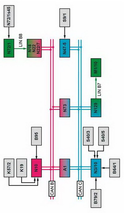
· A1 Instrument cluster
· B64/1 Brake vacuum sensor
· B79/2 Transmission neutral position sensor
· B95 Battery sensor
· K19 Battery decoupling relay
· K57/2 Additional battery relay
· M1/10 Starter generator
· N3/10 ME-SFI [ME] control unit
· N10 SAM control unit
· N18 HEAT [HAU] control and operating unit
· N22 AAC [KLA] control and operating unit
· N22/7 Comfort AAC [KLA] control and operating unit
· N47-5 ESP and BAS control unit
· N72/1 Upper control panel control unit
· N72/1s45 ECO switch
· N73 EZS control unit
· N129 Starter generator control unit
· S9/1 Brake light switch
· S40/3 Clutch pedal switch
· S40/5 Start enable clutch pedal switch
· CAN B Interior CAN
· CAN C Engine compartment CAN
· LIN B7 On-board electrical system LIN
· LIN B8 Climate control LIN